Ethernet Rings
Following on from my previous blog entry I will talk a little more about how we are able to create an Ethernet ring, and the options that we have to give us Ethernet Ring Protection.
Since Token ring fell out of favour and Ethernet has become the defacto standard network used in LAN and last mile services the most common network topology in use today is a star topology. You can almost guarantee that your office computer will be connected by a single cable (or fibre) to a central switch which then connects you to the rest of the network.
Star networks have many advantages over other topologies such as:
- Single node failure will not bring the network down
- Increased performance compared to bus topologies, although this relies on the central hub being a Layer 2 switch
- Ability to connect new nodes with no impact on existing node connectivity
In an office environment where nodes are added/removed on an ad-hoc basis these advantages far outweigh the extra cost required for the switch hardware. The biggest disadvantage to a traditional ethernet star topology when being used outside of an office environment is that you have a single point of failure. If your central switch fails or someone trips up over your cable ripping it out of the RJ45 socket then you lose connectivity.
In mission critical and industrial applications a single point of failure can not normally be tolerated. Loosing connectivity to a node on a production line could end up costing thousands in lost build time or could put workers at risk.
There are various ways of removing the single point of failure in a star network, the simplest is to double up on your connectivity, i.e two switches, two connections but obviously this means double the cost. There are protocols designed specifically for this topology such as IEC 62439-3 which will then monitor and control the flow of data over the duplicated links and handle when one of them fails.
Another way is to use our Ethernet Ring hardware that allows devices to be daisy chained together in a ring. This removes the need for any central switching hardware whilst still giving two links to each node. If one link, or node fails then connectivity to all other nodes in the network is maintained allowing communication to continue. The savings in switching hardware for networks that have a large number of nodes in them soon start to add up, and along with the simplicity in the network architecture means that for fixed topology networks we would recommend implementing a ring for a wide number of scenarios.
Normally connecting Ethernet devices together to form a ring will lead to one of two things: The networking hardware will detect that something is wrong and shut down the links, or the hardware will go into meltdown as a frame is sent around the network constantly flooding it with traffic.
Our hardware has been designed to facilitate intelligent switching, the hardware detects when it has received a frame with a source MAC address that matches the local node and removes it from the network. This allows a simple unmanaged ring to be created, where a node will forward its outgoing frames out of one port and drop it once it re-appears on the other. This does not give any redundancy but does remove the need to provide a central switch. For a network of hundreds of nodes this can represent quite a substantial saving in hardware costs.
For an advanced network configuration our hardware can be configured to provide a true redundant ring, be that using a standard protocol such as HSR, PRP or by using our own protocol.
Ethernet Redundancy
 There are number of protocols in use that provide redundancy. Whilst developing our hardware we are concentrating on supporting two standard protocols and are also developing our own. First lets look at the standard protocols:
Parallel Redundancy Protocol
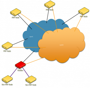
Parallel Redundancy Protocol (or PRP) is an IEC standard, IEC62439-3 Part 5, and consists of two similar but separate networks.
Each node is connected to two separate Ethernet networks and sends out Ethernet frames out via both networks at the same time. Under normal operating conditions the destination node will receive two copies of a particular frame discarding the 2nd frame based on a sequence number.
Since data is sent out over both networks a failure of one network will still mean that the target node will receive the data with zero fail over delays. The far end will detect that it has only received one frame and can then raise an alarm to the monitoring device.
Both Ethernet ports on a node respond to the same MAC address which means that any protocol stack that normally sits on top of layer 2 can run on a PRP network, albeit with a slightly smaller MTU due to the PRP protocol overheads.
Advantages
- Full-duplex 100Mbps connection end to end
- No fail over delay
Disadvantages
- Double networks means double the cost
- Without custom hardware each node receives duplicate frames increasing processor workload
High-availability Seamless Redundancy
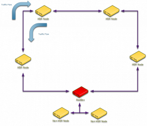 network to it’s intended target. In the case of uni-cast messages the frame will not be switched past the end node, for multi-cast a node needs to be able to detect that it has received a frame that it originally sent out and ensure that it is not switched back into the ring.As with PRP each node should receive a frame
twice as a node transmits its data both ways around the ring leading to zero fail over delays. Where HSR differs from PRP is that the available bandwidth is effectively halved due to double the data being transmitted over the same network for each transmission, however for large networks the saving in cost due to not having to buy multiple switches means that for low bandwidth applications HSR could be the preferred method.
Advantages
- No fail over delay
- Single network
- Integrated switches in nodes removes need for central switches
Disadvantages
- Half of the available bandwidth available
- Without custom hardware each node receives duplicate frames increasing processor workload
Roedan Redundant Ring
Roedan Redundant Ring (let’s call it RRR) is a system that we have designed specifically for our low power hardware.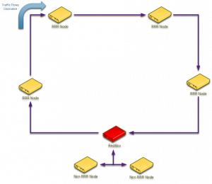
As with HSR an RRR network is wired in a ring. However in contrast to HSR during normal operation traffic is only sent 1 way around the ring from node to node. In the event of a break in the ring the nodes that lose connectivity detect the link drop via a dedicated link status interrupt and broadcast the error down stream. This is then picked up on each node which forces the nodes to enter a failed state. In this state data is sent in both directions around the ring, but since there is a break in the ring the nodes still only receive one copy of the frame. Once the broken link has been re-established the link status is broadcast from the nodes that detect the link change which then forces the network to only work in one direction again.
The time taken to broadcast the failure message is dependent on the number of nodes in the ring but due to the fast Ethernet switching capability this is only around 110us per node in the ring. This means that we can achieve a switch over delay of around 1ms for 110 nodes in the ring.
Currently we are fine tuning the ring nodes but a RedBox (Redundancy Box) is on our road map to allow the ring to communicate with the outside world. The RedBox will allow ring status to be reported to devices that do not support the RRR protocol.
Advantages
- Single network
- Integrated switches in nodes removes need for central switches
- Nodes do not receive duplicate frames
- Full network bandwidth available during non-fault cases
Disadvantages
- Variable fail over delay based on the number of nodes in the ring

